In previous blog Introduction
to data logic
We talked about the basics what is data logic and about
transistors now we will talk about
digital gates.
Digital
electronic circuits operate with voltages of two logic levels false and
truth (0&1). The range of voltages corresponding to Logic false is
represented with ‘0’. Similarly, the range of voltages corresponding to Logic
truth is represented with ‘1’.
The basic digital electronic circuit that has
one or more inputs and single output is known as Logic gate. Hence, the Logic gates
are the building blocks of any digital system. We can classify these Logic
gates into the following three categories.
- Basic gates
- Universal gates
- Special gates
1. BASIC GATES,
The basic gates are
· AND gate.
· OR gate.
· NOT gate.
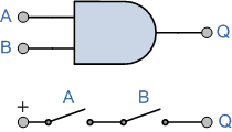
The first one is AND gate . An AND gate is a digital circuit that has two or more inputs
and produces an output, which is the logical AND of all those inputs.
The truth table of
2-input AND gate.
|
A |
B |
Y = A.B |
|
0 |
0 |
0 |
|
0 |
1 |
0 |
|
1 |
0 |
0 |
|
1 |
1 |
1 |
Here A, B are the inputs and Y is the output of
two input AND gate. If both inputs are ‘1’, then only the output, Y is ‘1’. For
remaining combinations of inputs, the output, Y is ‘0’.
Second one is OR gate . An OR gate is a digital circuit that has two or
more inputs and produces an output, which is the logical OR of all those inputs. . Between
which (+) is present.
the truth table of 2-input OR gate.
| A | B | Y = A + B |
|---|---|---|
| 0 | 0 | 0 |
| 0 | 1 | 1 |
| 1 | 0 | 1 |
| 1 | 1 | 1 |
Here A, B are the inputs and Y is the output of two input OR gate. If both inputs are ‘0’, then only the output, Y is ‘0’. For remaining combinations of inputs, the output, Y is ‘1’.
In simple words, there are two switches on a parallel line then any one switches should be turned on to light up bulb.
| A | Y = A’ |
|---|---|
| 0 | 1 |
| 1 | 0 |


No comments:
Post a Comment